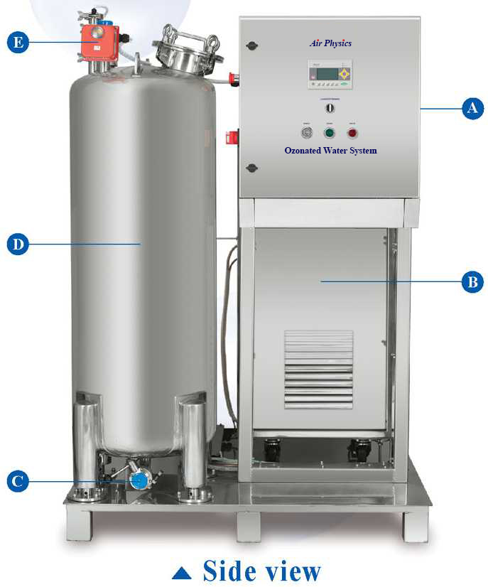
The Layout of the Ozonated Water System


        A. Control panel 

        B. Ozone generator

        C. Ozonated water outlet

        D. Water buffer tank

        E. EM valve (control

make up water )

        F. Water inlet

G. Ozone destructor

H. CO-mixer

I. Back stream leaking valve

J. Booster pump

K. Ozone sensor

L. Drain


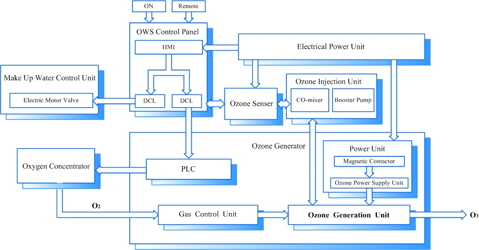
   Block Diagram


   Piping diagram


Specification


OWS-M

OWS-L

 Buffer Tank

Volume

0.2 m3

1.5 m3

Dimensions

Ø 50 x H170 (cm)

Ø 130 x H190 (cm)

Material

SUS304 or SUS316

 Water capacity

Up to 20 m3/h (85 gal/min)

Up to 40 m3/h (170 gal/min)

 Max. ozone concentration

Depend on the ozone generator

 Ozone generator

G-P20 / G-P30 / G-P40

G-P20 / G-P30 / G-P40 / V-80

 Oxygen supply

Built-in / Built-in / Built-in

Built-in / Built-in / Built-in / MX-12

 Ozone injection

 1. CO-mixer

 2. Booster pump

 3. Back stream leaking valve

 Dissolving ozone sensor

 Measurement range: 0.02-2.00 ppm

 Ambient ozone sensor

 Measurement range: 0-0.3 ppm

 Control

 PLC and HMI

 Power consumption

 1.8 kW (ozone generator and oxygen supply are excluded)

 Power supply

 AC 220-240 V, 50/60 Hz

 Dimensions

L140 x W140 x H190 (cm)

L200 x W160 x H210 (cm)


[Application Information]